

Overview
In this tutorial, we will learn about different ER Diagram components. An Entity-Relationship Diagram( ER Diagram) visually represents the data schema in a database system. It has many components, each representing various aspects of the data model. Understanding each component is essential when drawing an ER diagram.
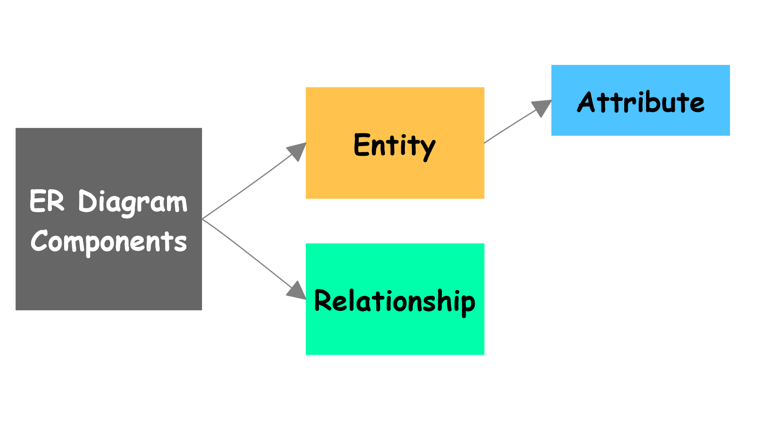
ER Diagram Components
The main components of an ER diagram are as follows:
- ➡️ Entity
- ➡️ Attribute
- ➡️ Relationship
- ➡️ Cardinality
Entity
Entities represent real-world objects or concepts about which data is stored in the database. An entity is represented as a rectangle in the ER diagram. Some examples of entities are:
Customer, Product, Employee, Order, etc.
Attribute
Attribute is a property or characteristic of an entity. Attributes provide further details about the entities to which they belong. An Attribute is represented as an oval connected to the corresponding entity. Some examples of attributes are:
CustomerID, CustomerName, ProductID, ProductName, etc.

Relationship
Relationships represent associations or connections between entities. They describe how entities interact with each other. A Relationship is represented by a diamond shape connecting the related entities. Some examples of relationships are:
“Customer places Order,” “Student takes Course.”
Cardinality
Cardinality defines the number of occurrences of one entity associated with the number of occurrences of another entity. It’s usually indicated near the relationship lines using notations.
—
MySQL Tutorials
MySQL Tutorials on this website:
For more information on MySQL Database: